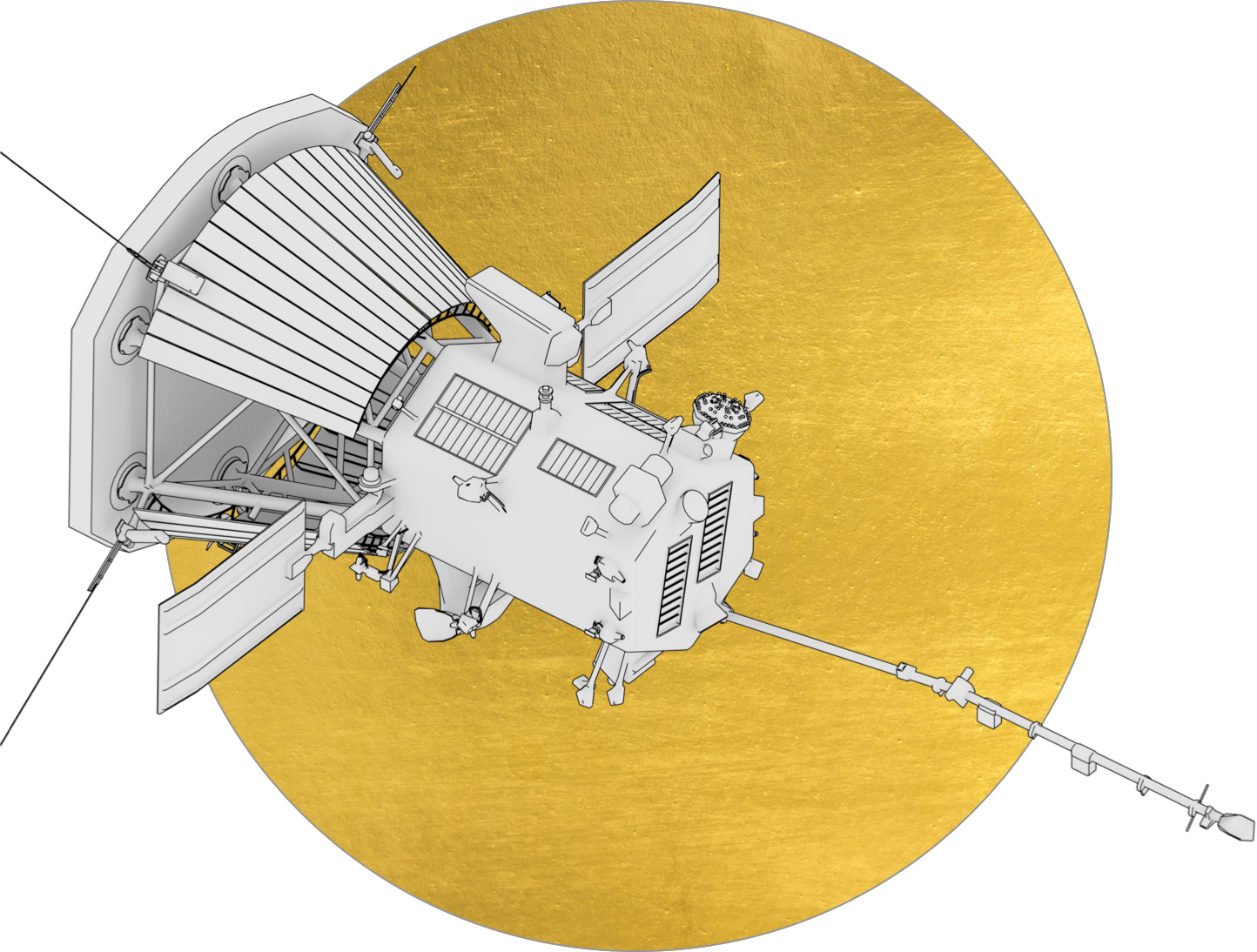
Parker Solar Probe
Advanced Paper Model
Cardstock is used for a wide variety of paper crafts, including greeting cards, paper flowers, origami and modeling. While some models require expensive materials and tools to assemble, paper models are accessible and easily assembled with paper, scissors and glue.
The popularity of paper models — especially replicas of actual launch vehicles and spacecraft at accurate scales — continues to grow. Detailed cardstock models, made for more experienced users, are often showcased in libraries, schools, museums and science centers.
Download the Materials List and Instructions below to build your own Parker Solar Probe advanced paper model!
For your convenience, we’ve also create a scrollable carousel of instructions below.
Parker Solar Probe paper model design by Zach PaperSat Design. These materials may be distributed freely for educational or informational purposes, under NASA’s Media Usage Guidelines. Learn more at www.nasa.gov/multimedia/guidelines/index.html.
Materials List Print
- Scissors or Craft knife (optional)
- Super glue
- Hot glue gun (optional)
- Cardstock (white)
- Single hole punch
- Safety ruler
- 4 acrylic rods (or similar material):
- 0.06 in (1.5 mm) diameter
- 2 in (5 cm) long, brown
- 2 wooden dowels:
- 0.0625 in (2 mm) diameter
- 4.5 in (11.5 cm) long
- 10 wooden toothpicks tips (colored yellow)
- 18 plastic broom straws (grey)
- Thin music wire or similar material (6 in or longer)
- Grey or silver paint
Advanced Model Instructions Carousel
Step 1
Cut out all blue areas on parts 1 and 5, including the three small blue circles near the bottom of part 1. Glue 2, 3, 4 and 6 to the backs of 1 and 5 as shown. Make very small holes in the two red dots near the top of 1 (only large enough to fit the diameter of the music wire snugly).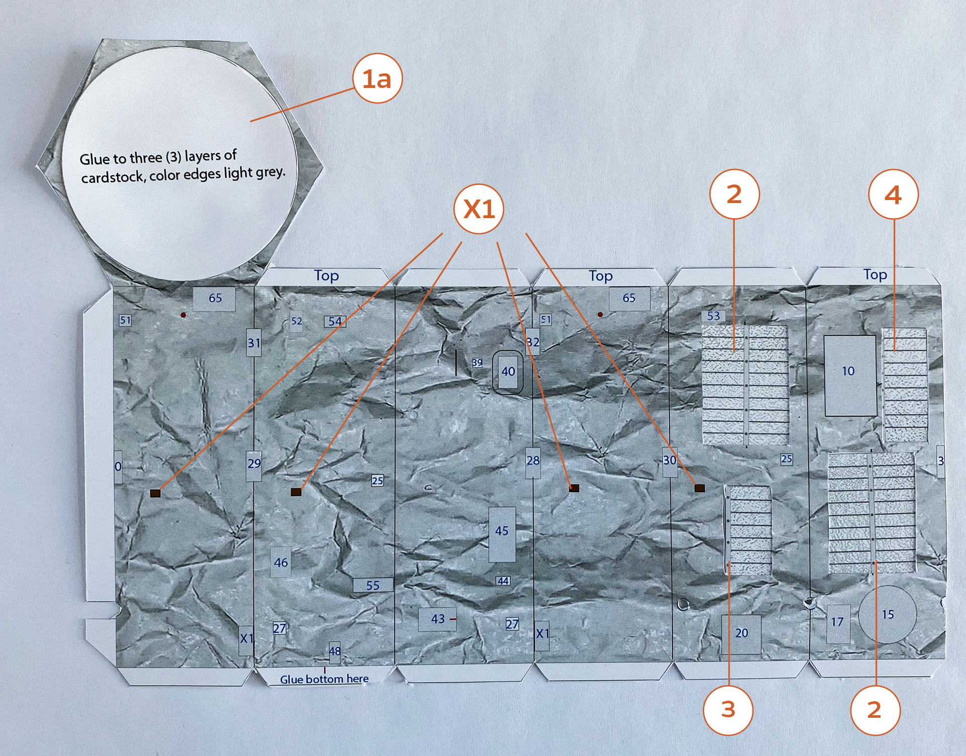
Step 2
Glue 5 to the marked tab on the bottom of 1 as shown.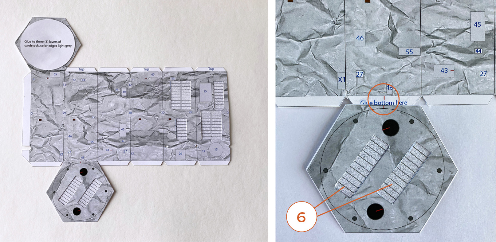
Step 3
Fold on the vertical lines to make an octagonal shape and glue 1 and 5 to the top and bottom tabs, respectively.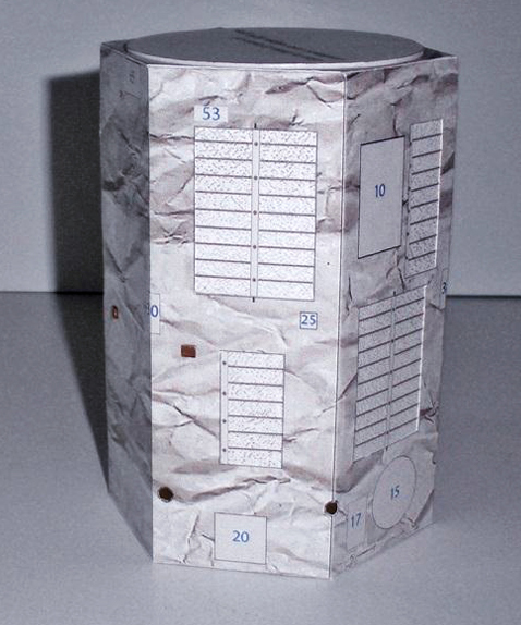
Step 4
Align the seams on 7 to the red lines on the black circles on the bottom.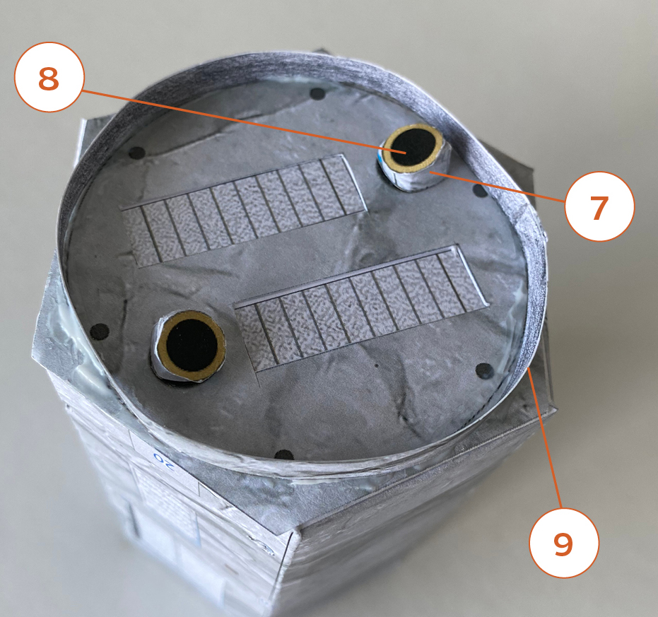
Step 5
Fold small tabs on 12 and 13 as shown. Glue on the matching graphics on 10.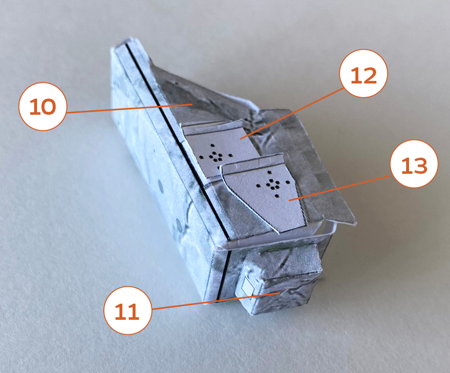
Step 6
Glue to the labeled area on the body as shown.
Step 7
Roll 14 into a thin hexagon drum. Roll 15 to an angeled cone. Glue 14 to the side of 15 with the blue marker. Match the seam on 15 to the red line on 14.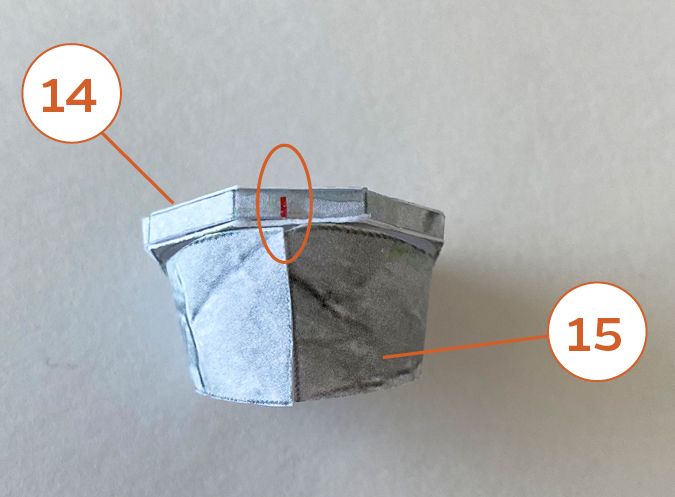
Step 8
Glue 16 to the other side.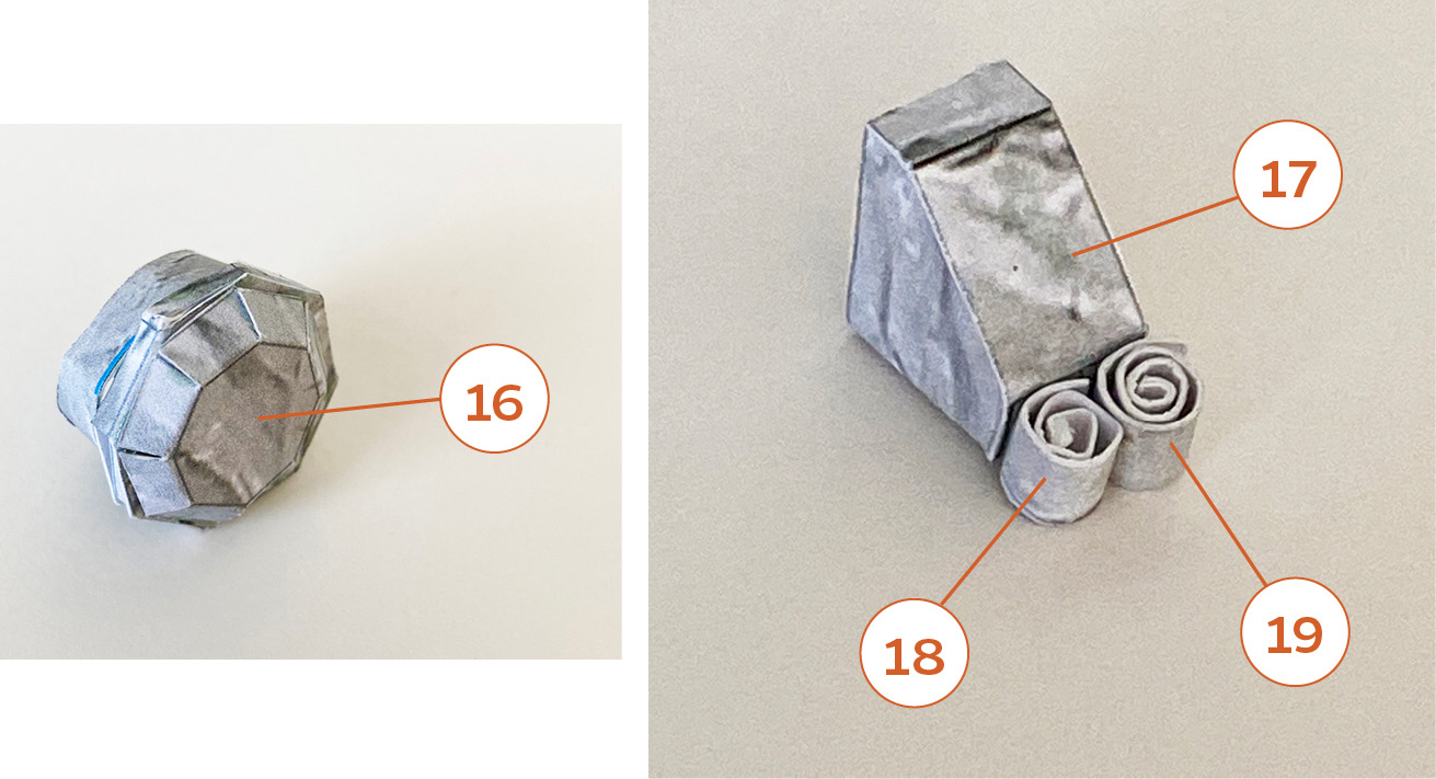
Step 9
Glue to the labeled areas on the body as shown.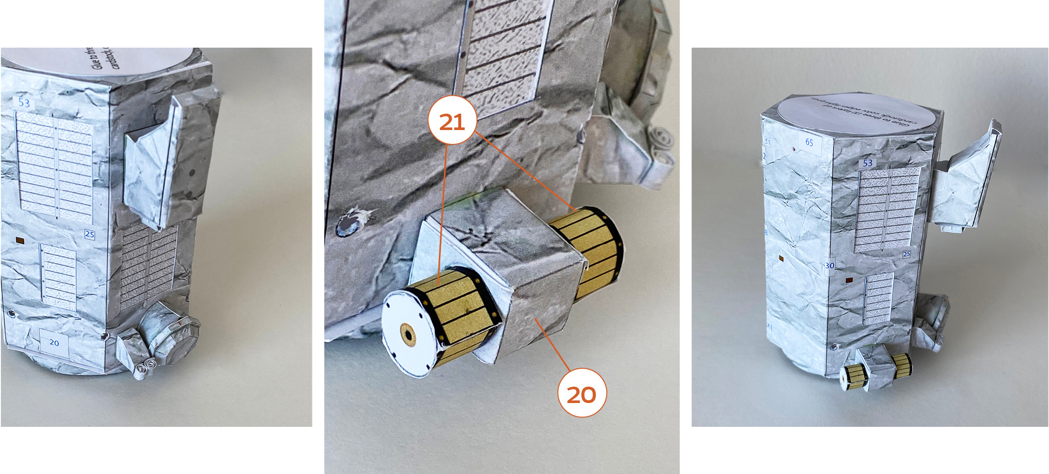
Step 10
Make three (3) of these assemblies. Roll 22 into to tight solid paper rods. Cut an angle to one end as shown on page 3 of the parts file.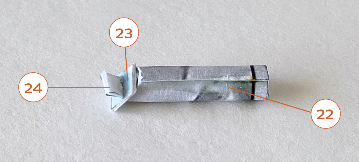
Step 11
Glue into the three small holes near the bottom up to the black line with the angled side downward.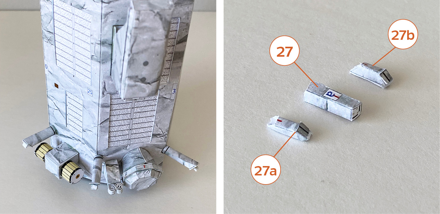
Step 12
Glue 27a and 27b to the labeled sides on 27. Make two of these. Glue 24 on the black lines as shown.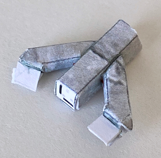
Step 13
Glue to the labeled squares near the bottom of the body with an upward angle as shown.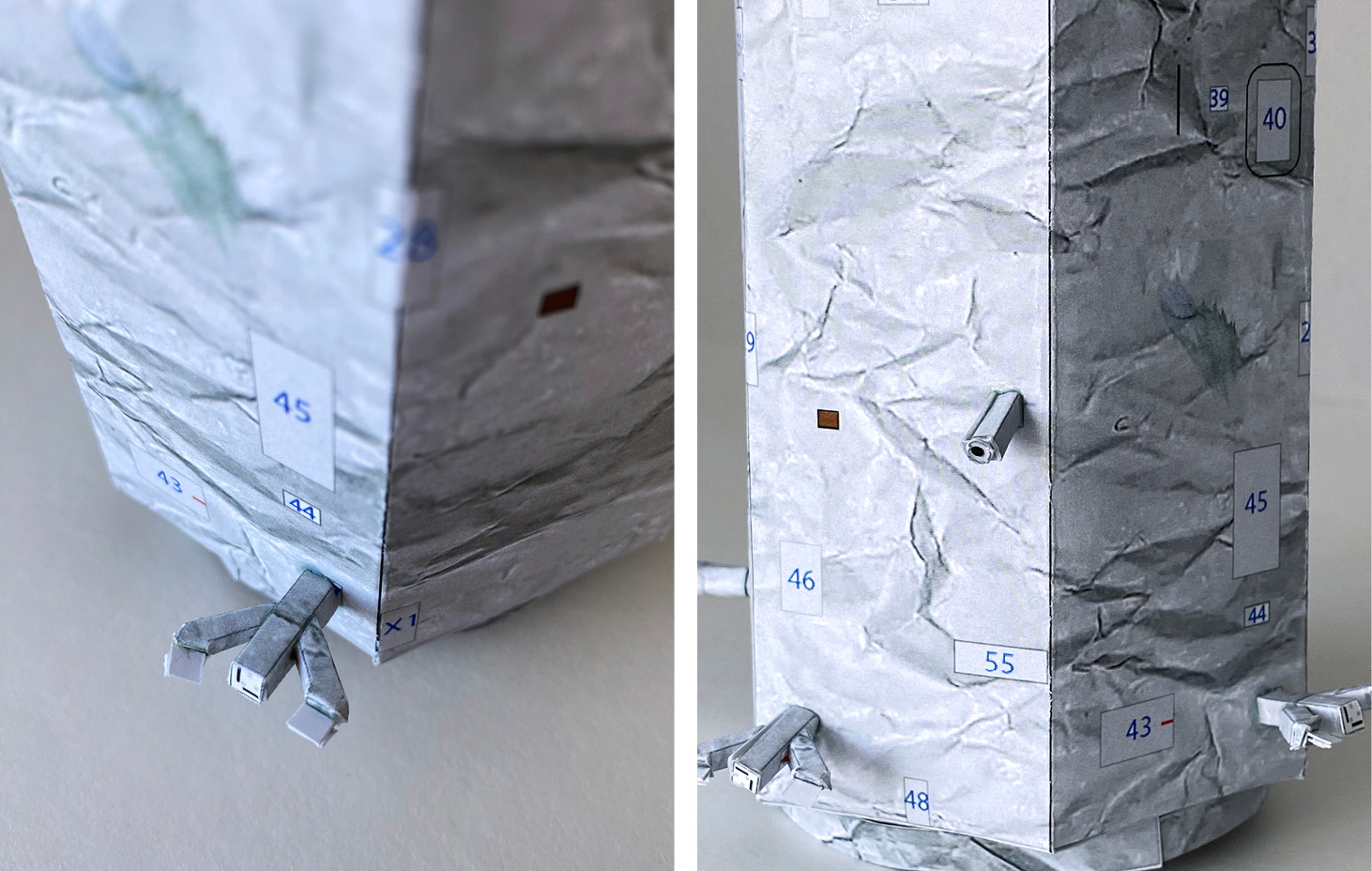
Step 14
Glue 28a and 29a to the labeled squares on 28 and 29 as shown.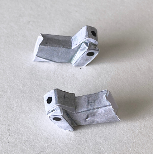
Step 15
Need 10 flattened pointed tips from toothpicks cut ~3 mm ( 0.12 in) long, colored dark yellow. Glue to the black dots on 28, 28a, 29 and 29a as shown.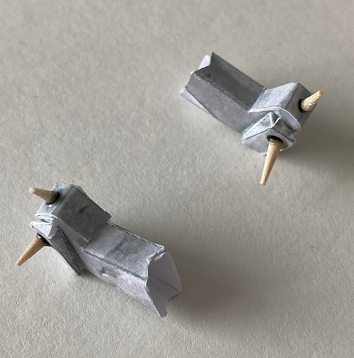
Step 16
Glue to the labeled squares on the body as shown.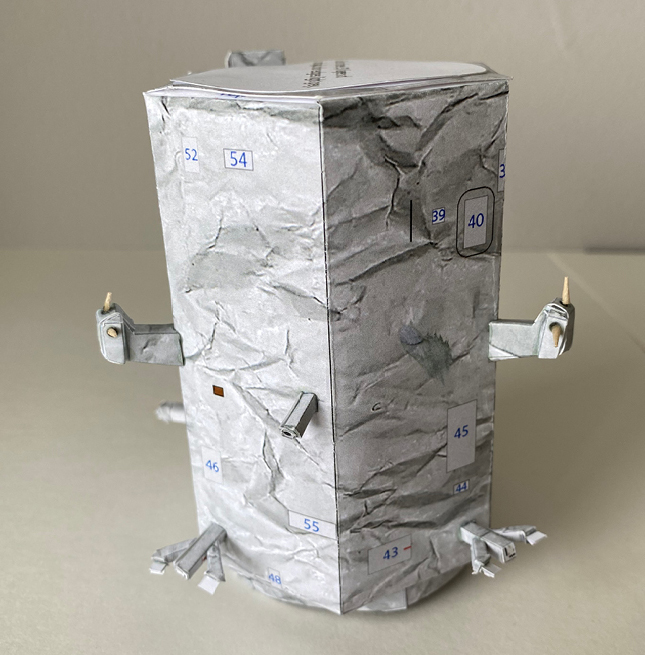
Step 17
Part 30 with painted end of the toothpick. Make two of these and glue to the labeled squares on the body.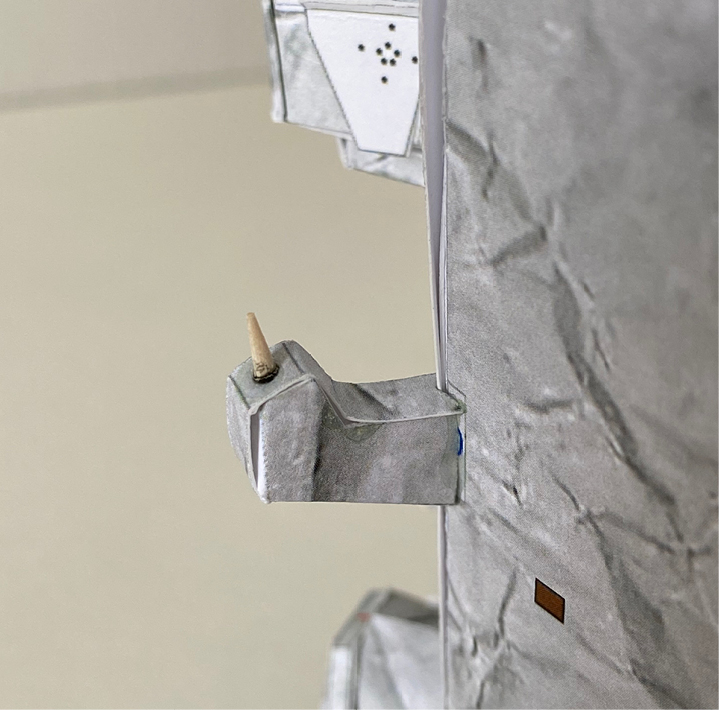
Step 18
Parts 31 and 32 with painted end of toothpick.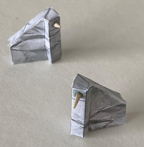
Step 19
Back view of 31 and 32.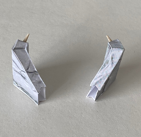
Step 20
Glue to the labeled squares on the body near the top as shown.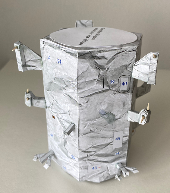
Step 21
Part X1. Make two of these with painted end of toothpick.
Step 22
Glue to the labeled squares on the body near the bottom as shown.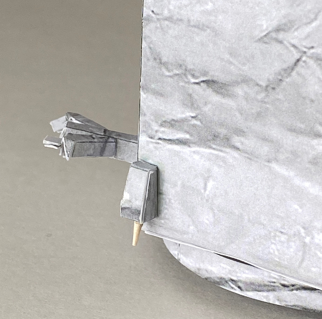
Step 23
Side 1.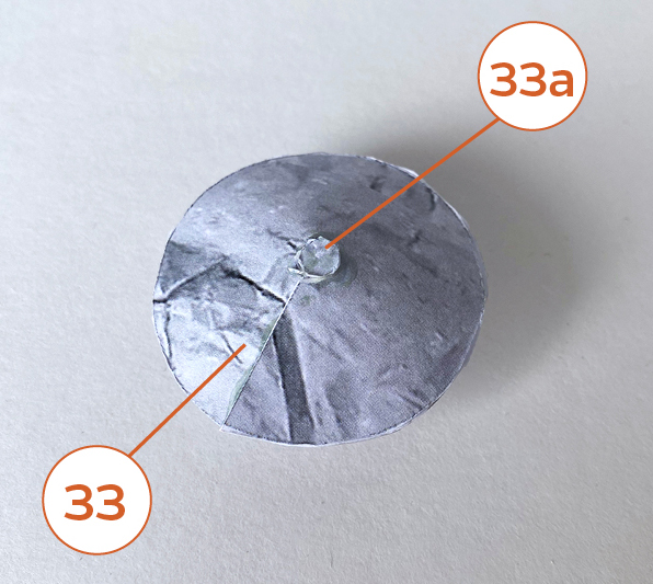
Step 24
Side 2. Glue the two dishes as shown.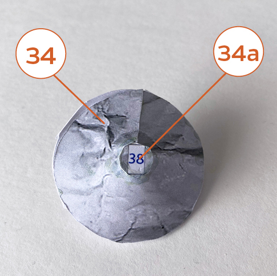
Step 25
Glue 38 to 34a as shown.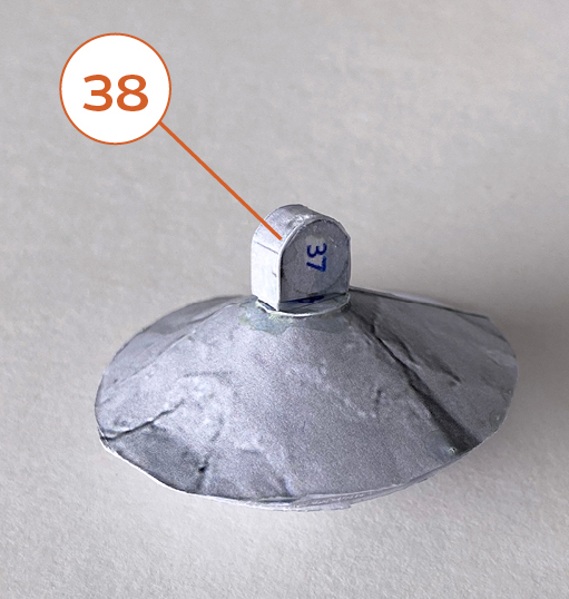
Step 26
Align the red markers on 36 and 37 as shown and glue on 35.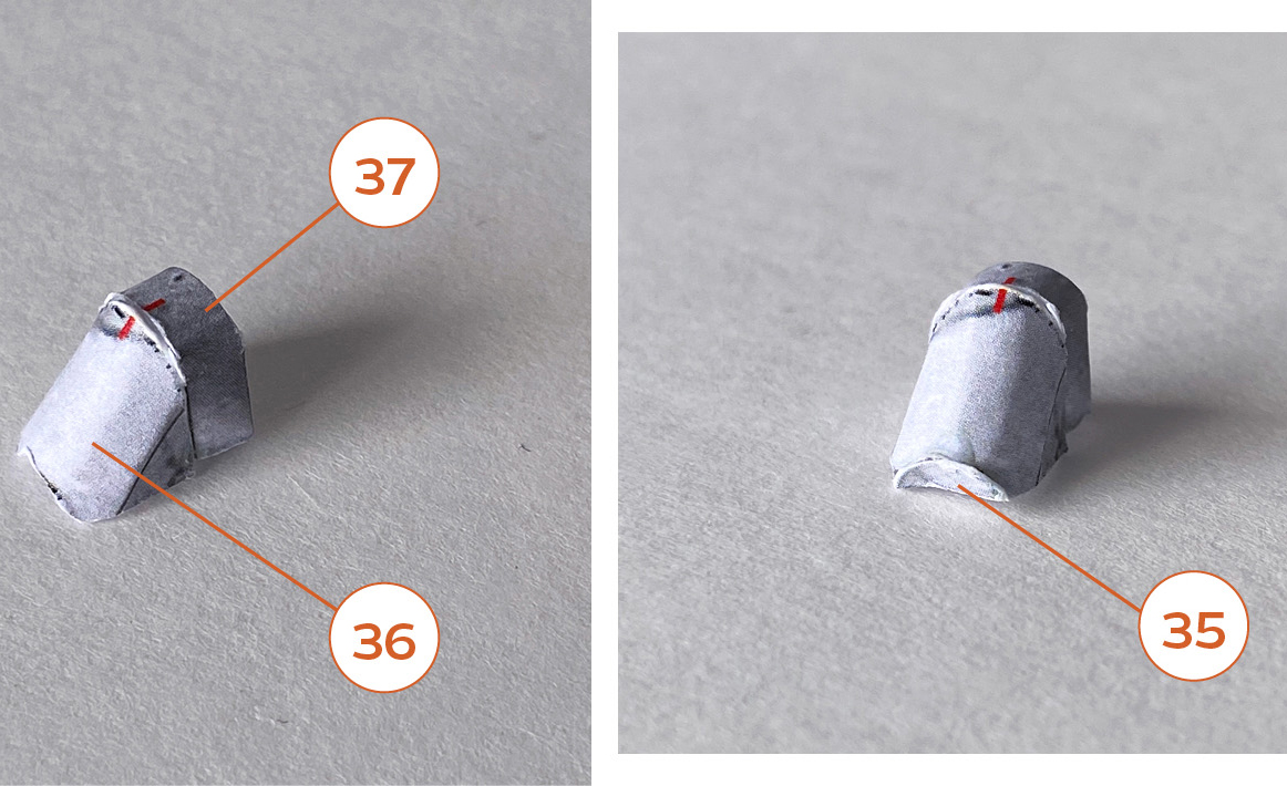
Step 27
Glue 39 and 40 onto the labeled areas on the body as shown.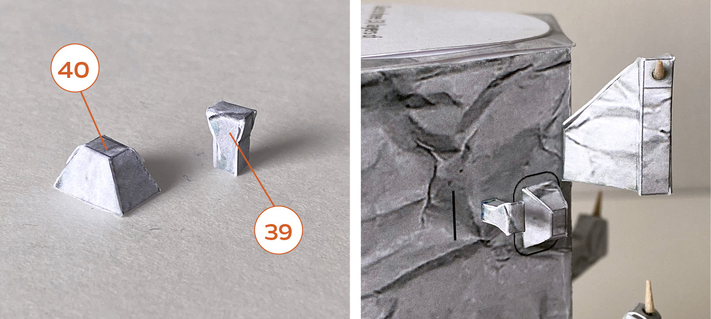
Step 28
Glue 36-37 onto 38 on the dish as shown. You can angle the dish up, down or straight.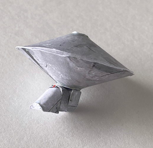
Step 29
Glue 44 and 45 onto the labeled areas on the body as shown. Part 44 should be angled downward.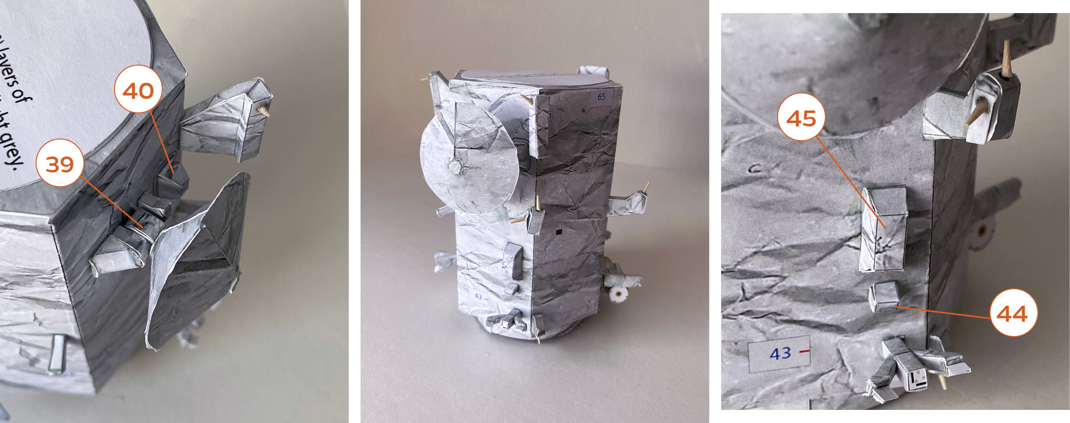
Step 30
Align the red markers on 41 and 41a and glue together.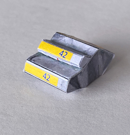
Step 31
Other side of 41 and 41a.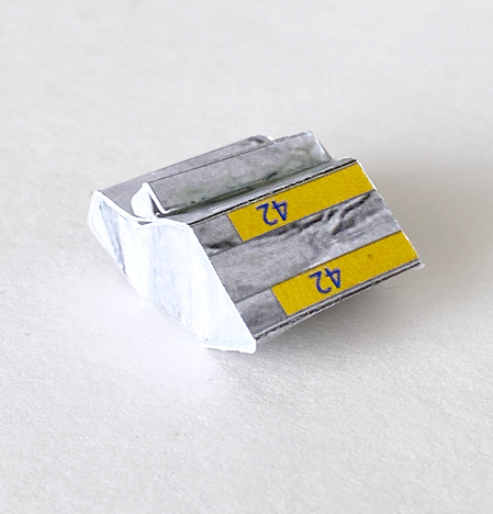
Step 32
Align the red marker on 43 to the red marker on the bottom of 41.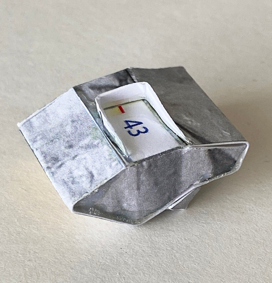
Step 33
Roll 42 to half circle tubes. Glue over the yellow areas as shown (see next photo).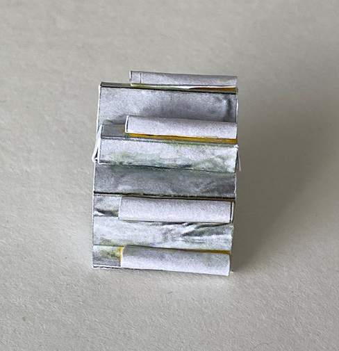
Step 34
Glue onto the labeled area on the body as shown.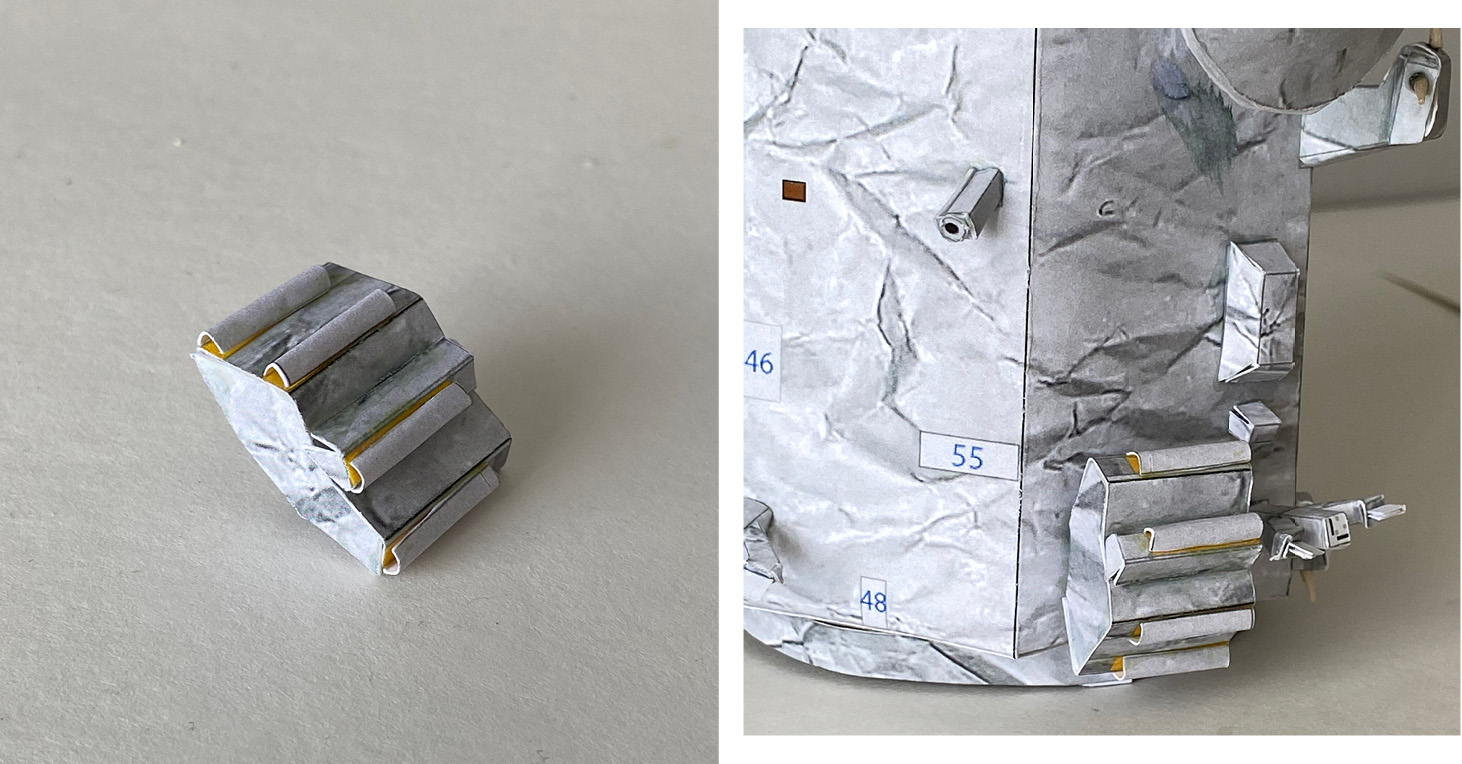
Step 35
Match the line of 57 to the seam on 58. Match the seam on 58 to the red marker on part 55.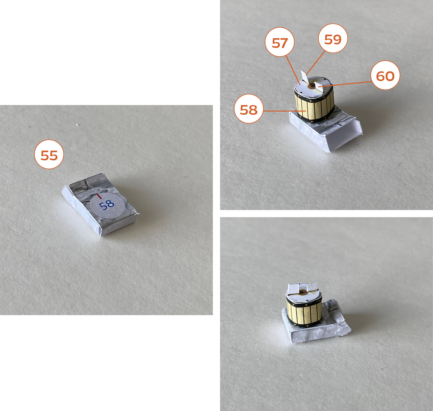
Step 36
Glue 56 to the bottom.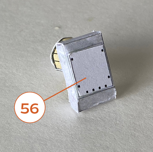
Step 37
Glue to the rectangle labeled “55” as shown. Glue 46 as shown.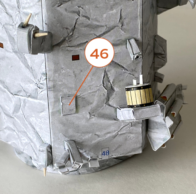
Step 38
Make two of 51. Glue onto the labeled areas on the body as shown.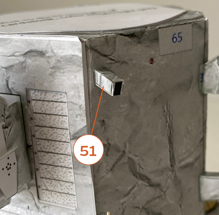
Step 39
Glue 52 and 54 onto the labeled area on the body as shown.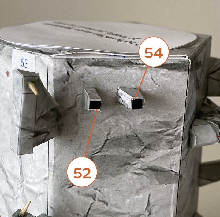
Step 40
Glue 53 onto the labeled area on the body as shown.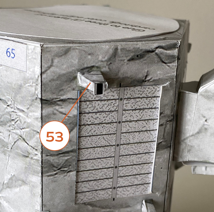
Step 41
Prepare four (4) acrylic rods according to the instructions on page 3 of the parts file. Glue one end to a small brown square in the middle of the spacecraft body and glue the other end onto the bracket above it as shown.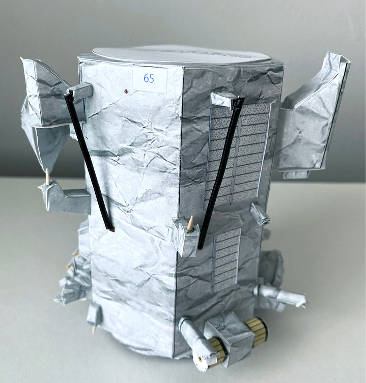
Step 42
Other side of the body.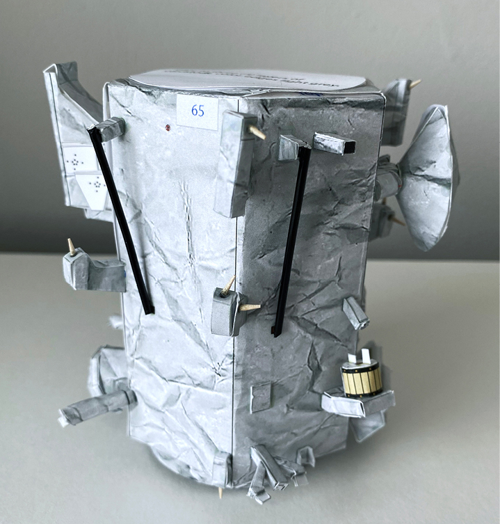
Step 43
Prepare two (2) wooden dowels according to instructions on page 4 of the parts file.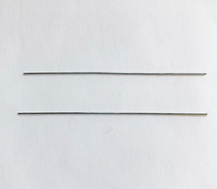
Step 44
Fold 47 with color inside, and fold 48 with color outside. Glue as shown for strength.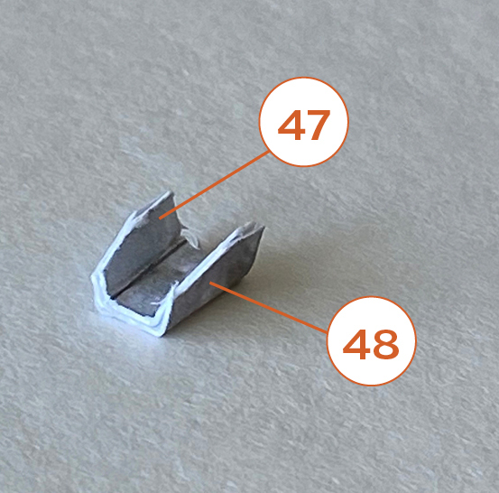
Step 45
Glue 47 and 48 onto the labeled area on the body near the bottom as shown.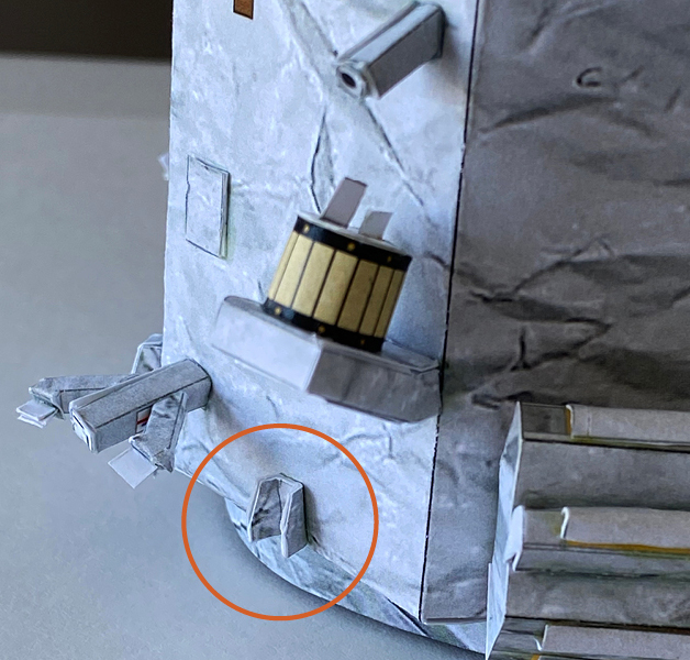
Step 46
Prepare 49 and 50 the same way as 47 and 48. Glue 49 inside 50 for strength.
Step 47
Glue onto end of one of the dowels as shown.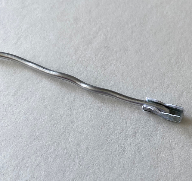
Step 48
Use the guide on page 4 of the parts file to glue these parts onto the second dowel (without 49 and 50).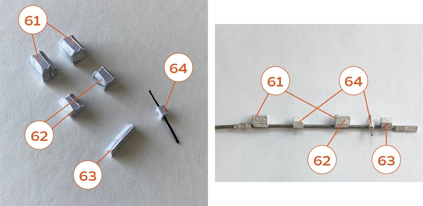
Step 49
Note the locations and angles.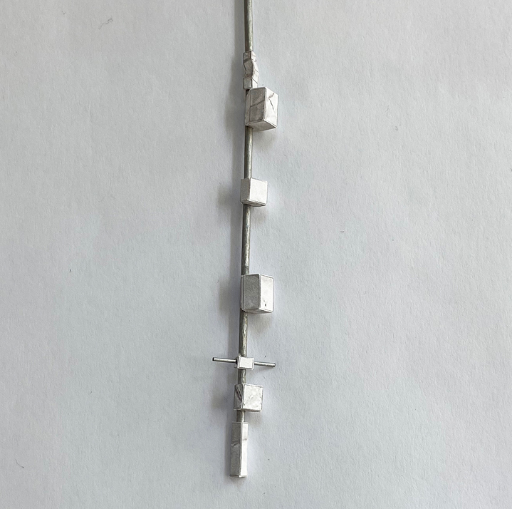
Step 50
Glue to the other dowel with the hinge (parts 49 and 50) as shown. This is the magnetometer arm. Set this to the side for now.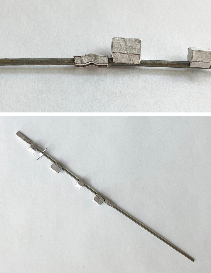
Step 51
Make two of 65 and glue onto the labeled areas near the top as shown.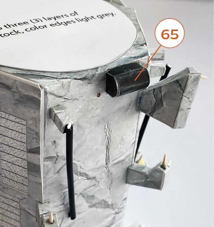
Step 52
Make two solar panel assemblies. Glue 68 inside to circular areas in 67 as shown.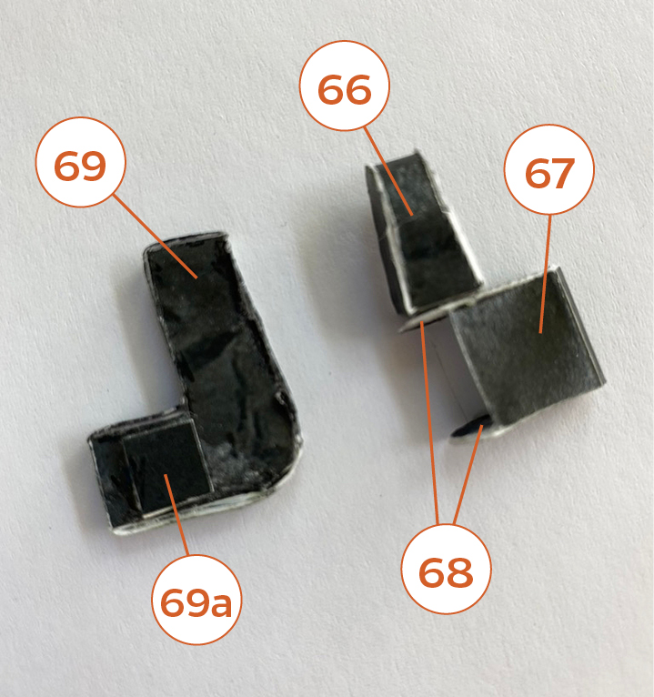
Step 53
Slide 69 inside 67 and glue in place.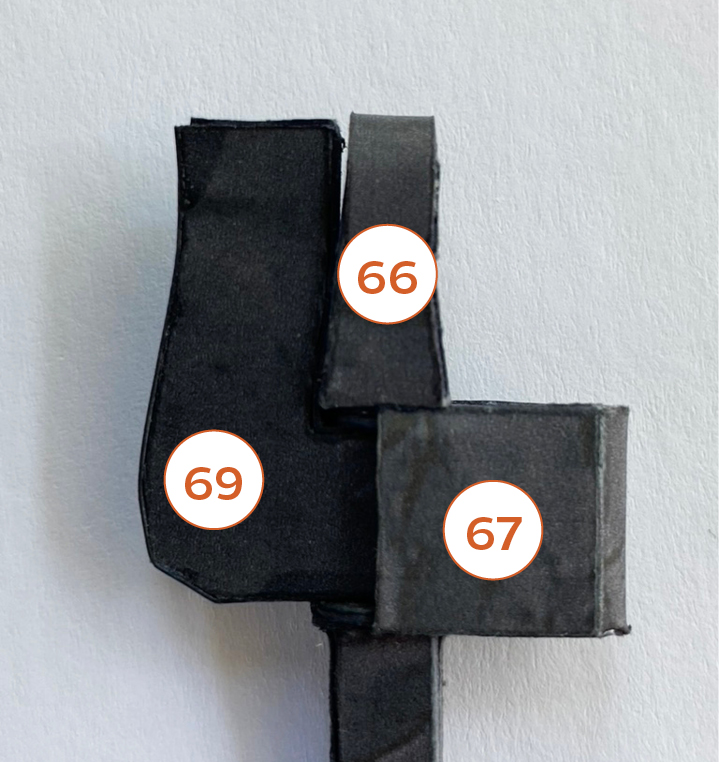
Step 54
Top view.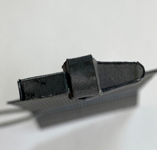
Step 55
Should look like this.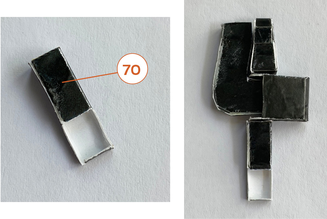
Step 56
Make two of 71. Fold and glue the solar panels back-to-back. Fold the lower area up just a little at the blue line as shown.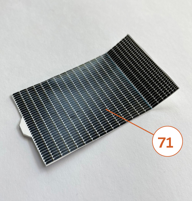
Step 57
Glue solar panels as shown above and in next photo.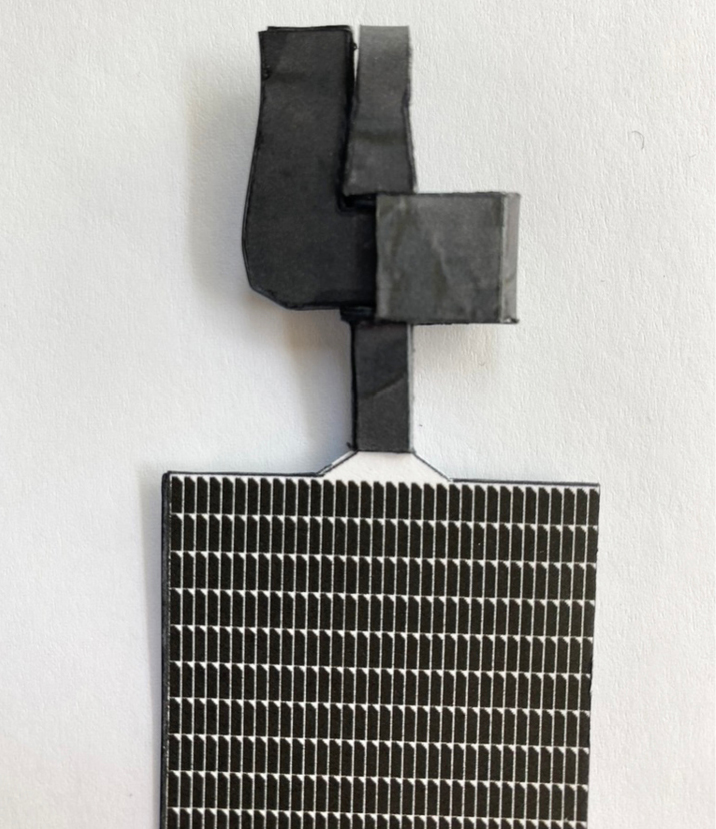
Step 58
Cut thin music wire or similar material according to instructions on page 5 of the parts file. Slide the wire through the two holes you made in the two small red dots at the top of part 1. The wire will support the solar panels.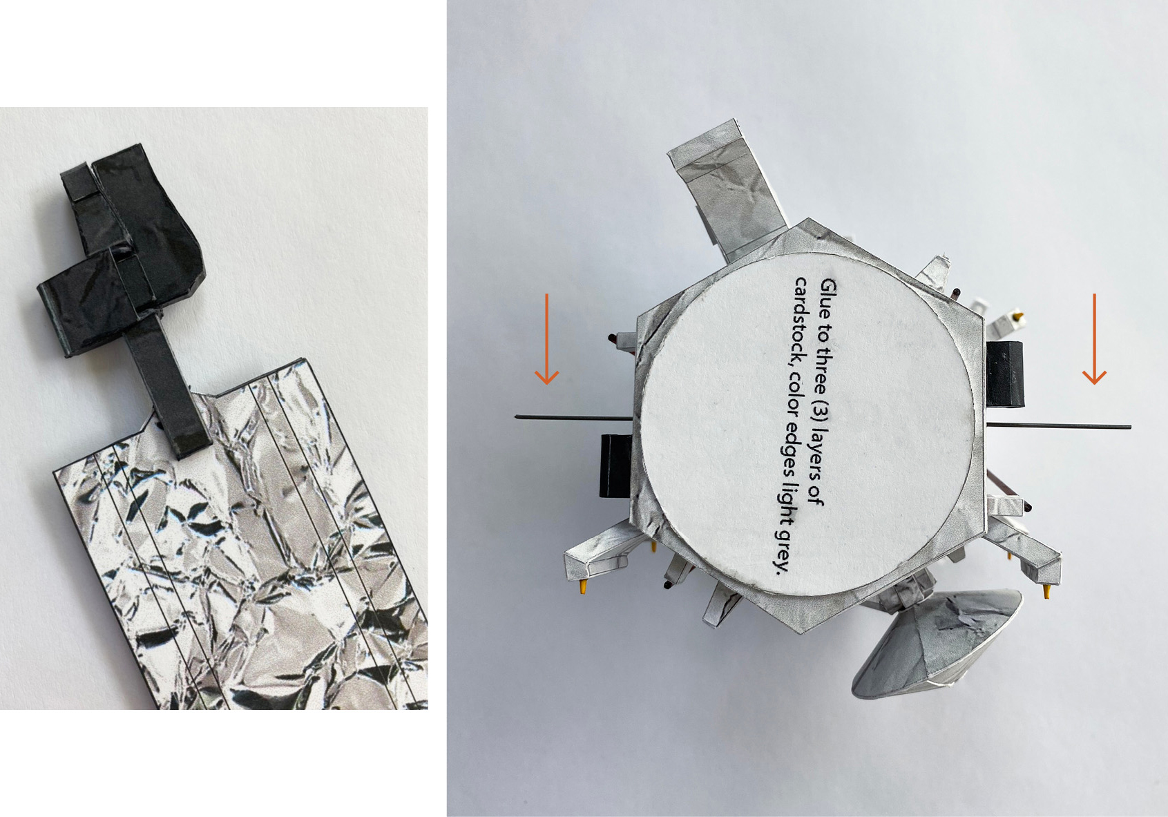
Step 59
Glue the two solar panel assemblies (on the part 65 side) onto the labeled area on the spacecraft body as shown. Rest the assembly on the support wire.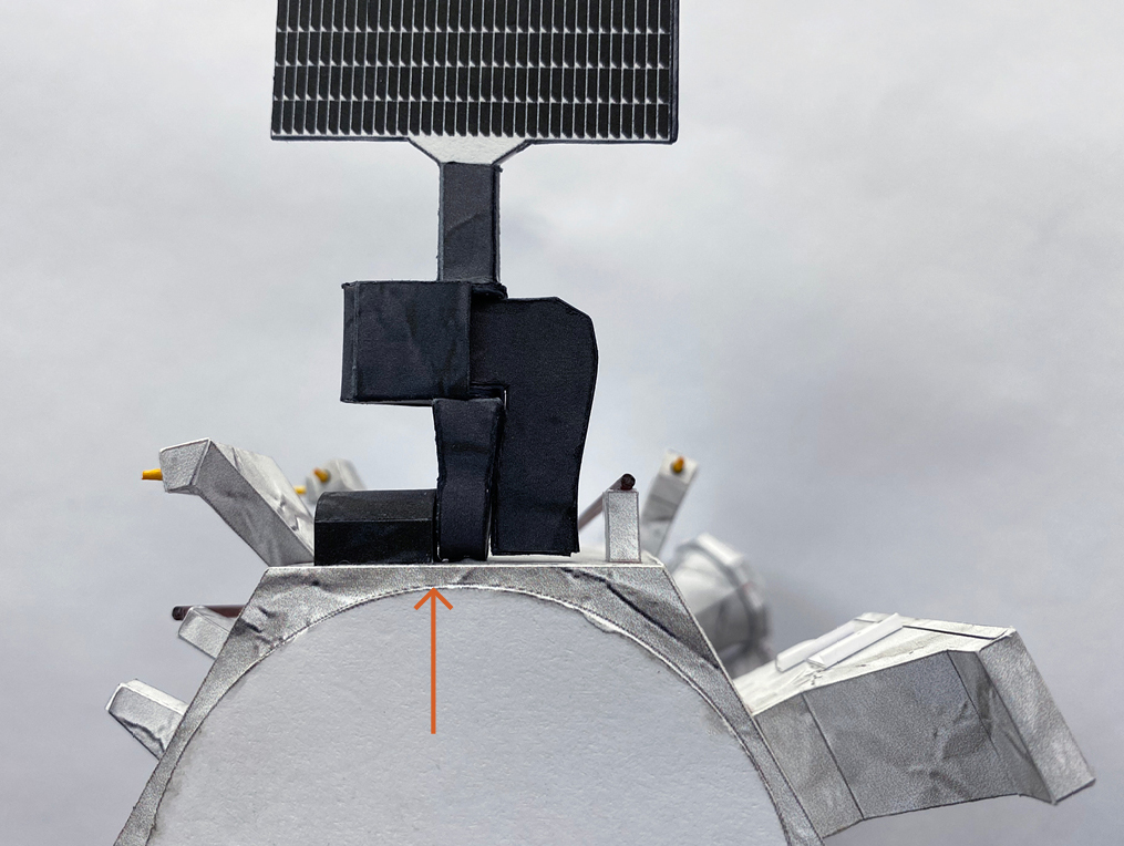
Step 60
Part 72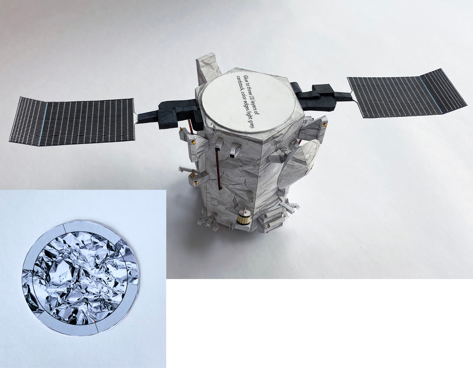
Step 61
Glue 72a to the back side of 72. The large hole you cut out on 72a should help to align the top perfectly with the body.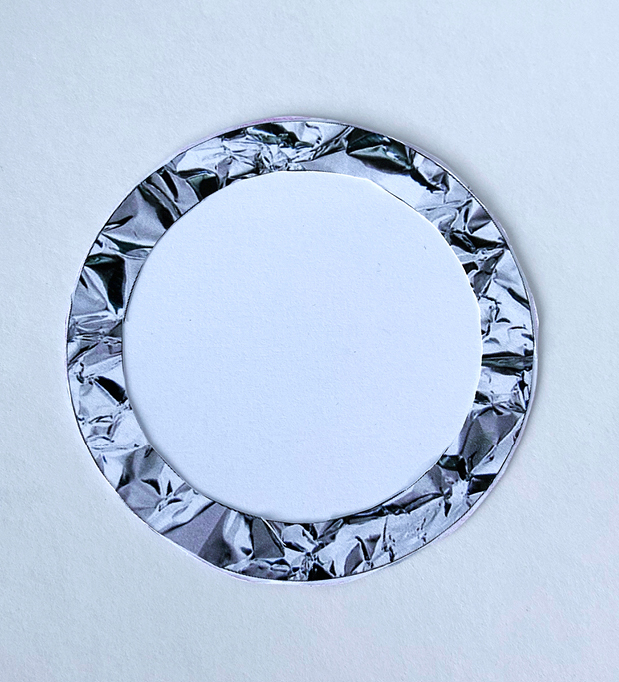
Step 62
Part 73A only — Glue X onto the small grey squares as shown. If you plan to use the paper parts on page 8 of the parts file (instead of substituting with toothpicks or lollipop sticks), cut an opening along the blue line on the right side of 73A.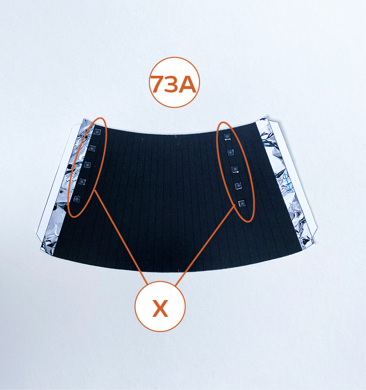
Step 63
Part 73B only — Glue 77 and 78 as shown. Glue X as shown. If you plan to use the paper parts on page 8 of the parts file (instead of substituting with toothpicks or lollipop sticks), cut an opening along the blue line on the right side of 73B.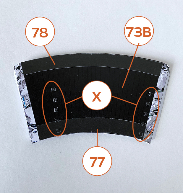
Step 64
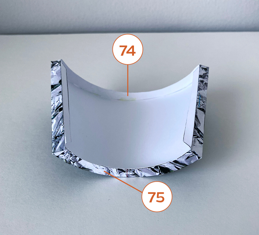
Glue 73A and 73B assemblies around the outer edges of 74 and 75 as shown. Align red center lines as shown. See important tips below.- Remember to glue 73A and 73B around the outer edges of 74 and 75.
- To help prevent the radiators from warping, start by gluing the center of 75 to the center bottoms of 73A and 73B while aligning the red lines. Then glue out from the center red line to one end. Repeat for the other end.
- Use the same method when gluing the center of 74 to the center tops of 73A and 73B.
- Follow all instructions about alignment of parts.
Step 65
Glue 76 to the inner edges of 74 and 75, aligning the red lines.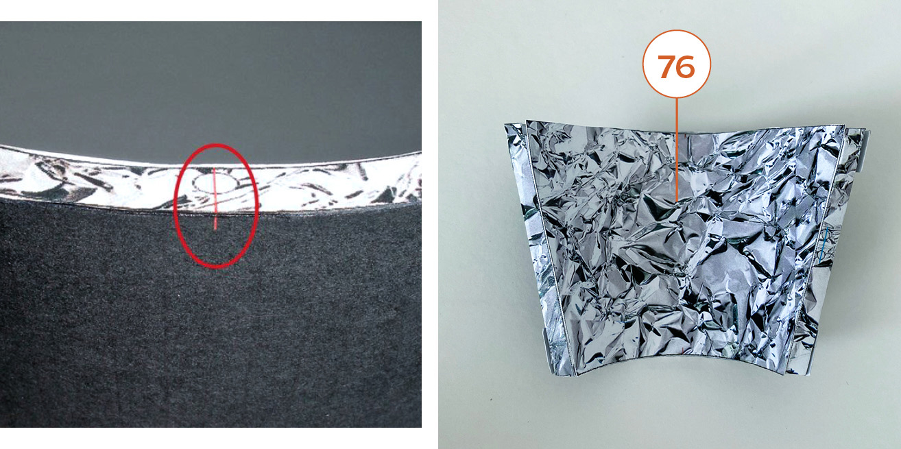
Step 66
Glue 79 to 74 over the six blue circles. Important: Align the seam of 79 to the red line on 74.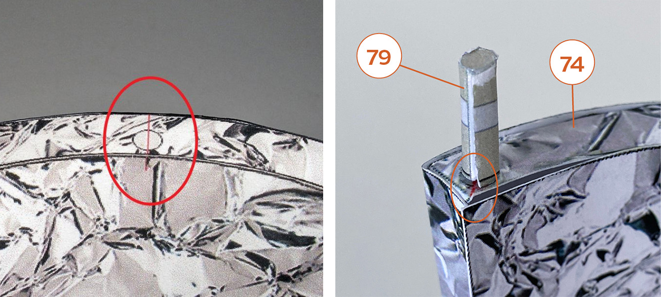
Step 67
Do this for all six poles.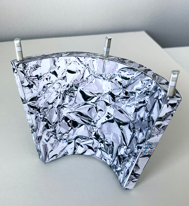
Step 68
Glue the 75 side of the two radiator assemblies to 72. Important: Align the lines on 72 to the red lines on the radiator assemblies. The six poles should angle outward.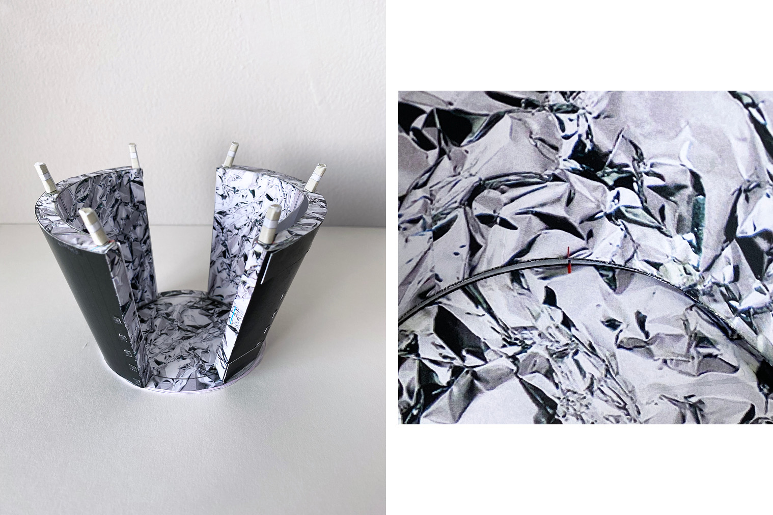
Step 69
The following parts may need trimming for proper fit. Glue on the grey sections on the poles. For a more realistic look, you can use long toothpicks or paper lollipop sticks colored light grey or silver in place of the paper parts.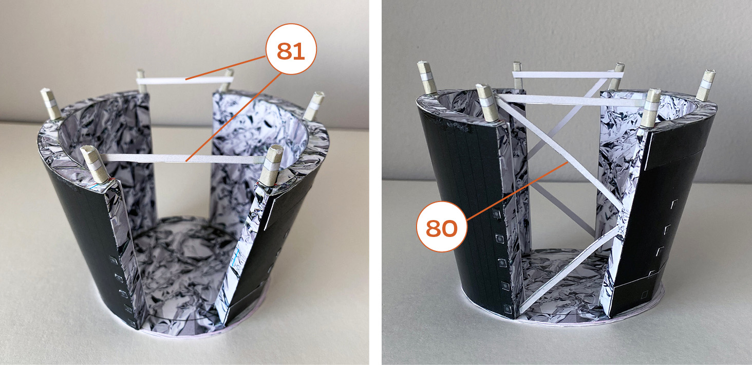
Step 70
The tab on 80 is inserted into the openings on 73A and 73B. If using toothpicks or lollipop sticks instead of the paper part, glue one end of the stick on the circle on the side of 73A and 73B.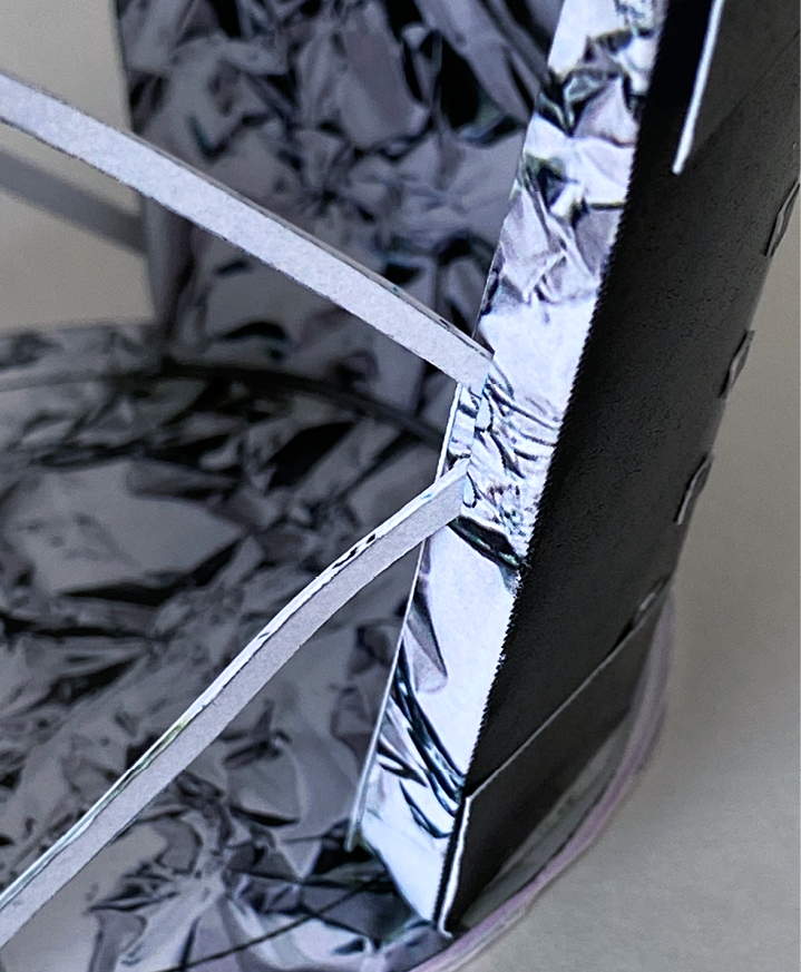
Step 71
Parts 82.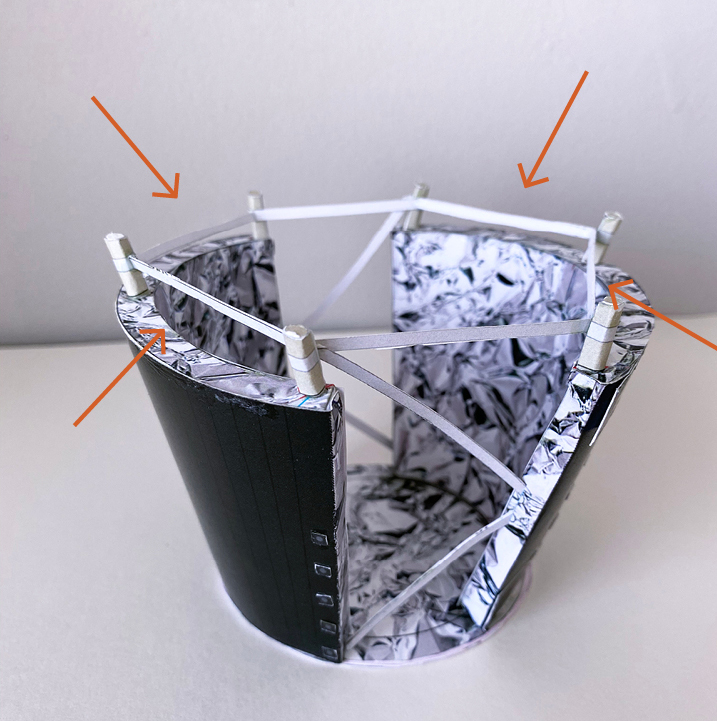
Step 72
Make two of these. Score and fold the small tabs of 83 and 84 along the blue line. Glue only the tabs together.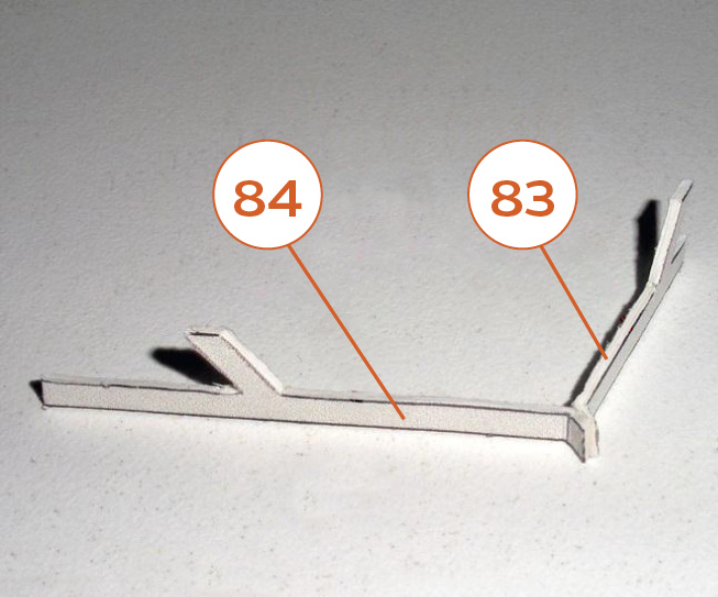
Step 73
See the parts placement illustration on page 8 of the parts file and the next photo to position and attach 83-84.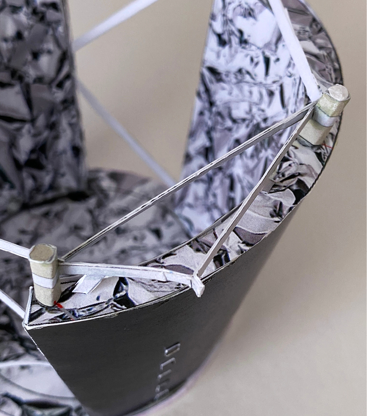
Step 74
Very important: Align 85 with the blue line. Do the same on the other radiator. See the guide on page 8 of the parts file for reference.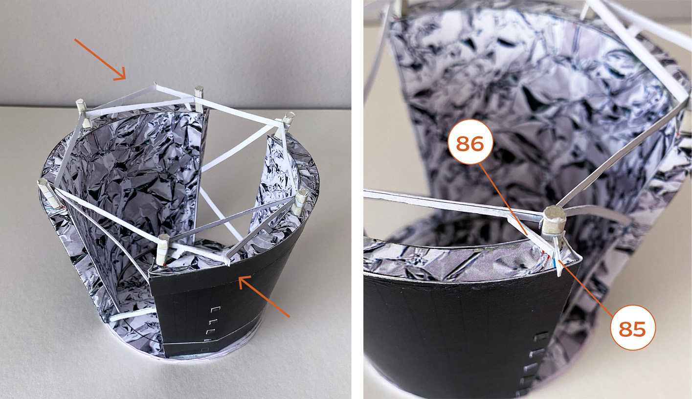
Step 75
Glue a piece of cardstock, cut to the same shape, to the back side of 90 for strength.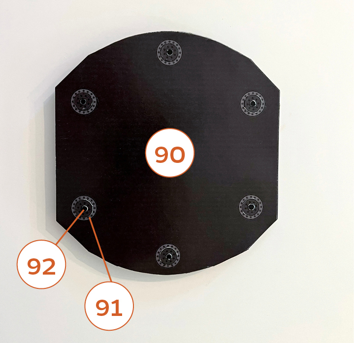
Step 76
Glue 90 to 88 as shown.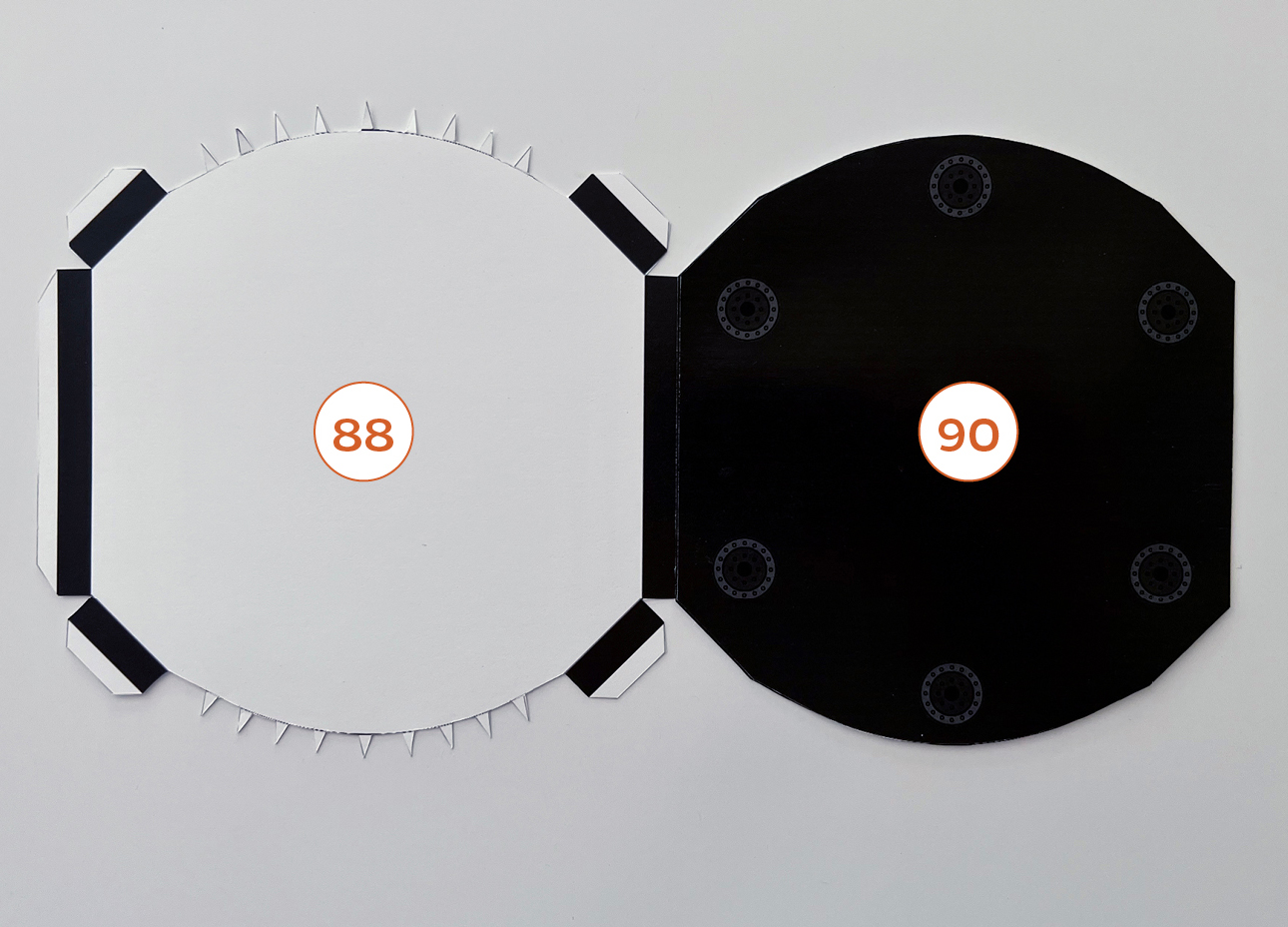
Step 77
Flip over and glue 89 to the triangle tabs of 88. Glue the internal support rings to the inside of 90 as shown, and then glue the inside edges and rings of 90 to 88 and 89.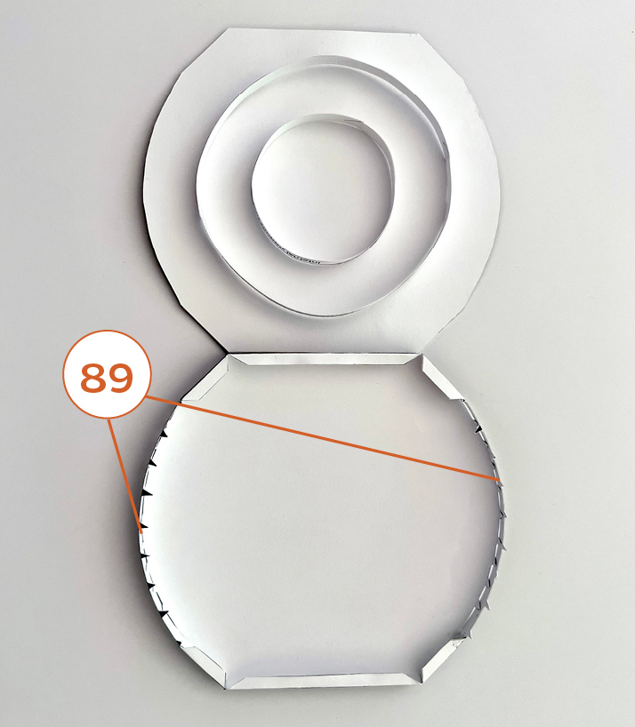
Step 78
Under side of heat shield.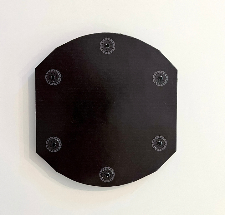
Step 79
Top side of heat shield.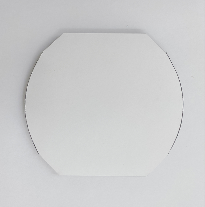
Step 80
Glue 87 to 85 (left) and to the tab of 83-84 (right) as shown. Do the same on the other radiator. They should have a downward tilt. Glue 97 to cardstock and then glue back-to-back with 98. Assemble 93-96 as shown. Position the black line of 96 perpendicular to the straight edges of 93 as shown in the second image.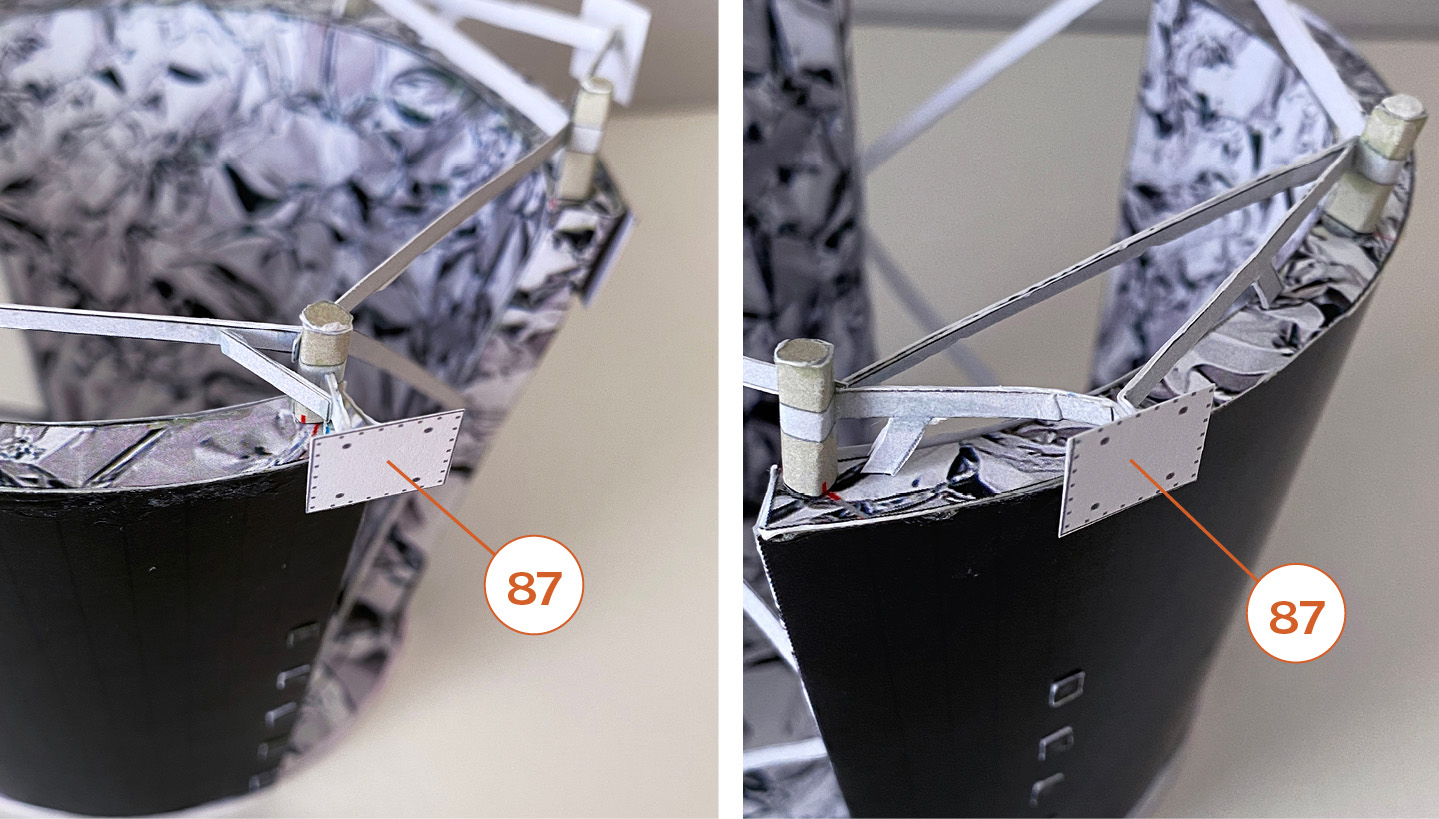
Step 81
Glue 97-98 on the black line of 96 as shown.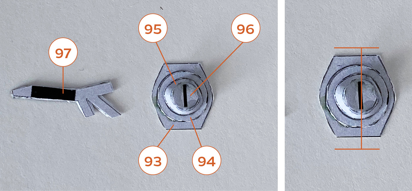
Step 82
Important: Glue onto the middle pole of the radiator without the two black strips (77 and 78).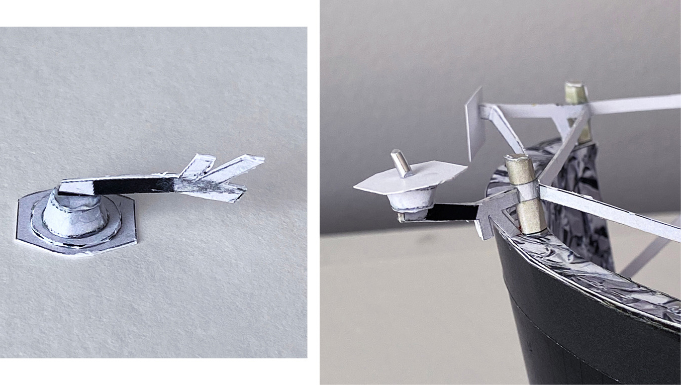
Step 83
Cut a piece plastic broom straw according to instructions on page 10 of the parts file. Color it light grey or silver and attach as shown.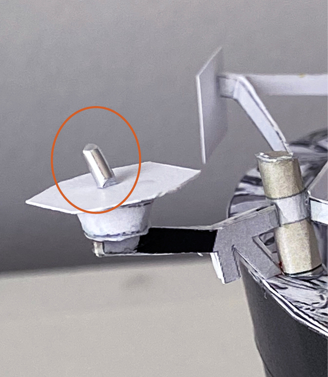
Step 84
Glue 87 to 97-98 as shown.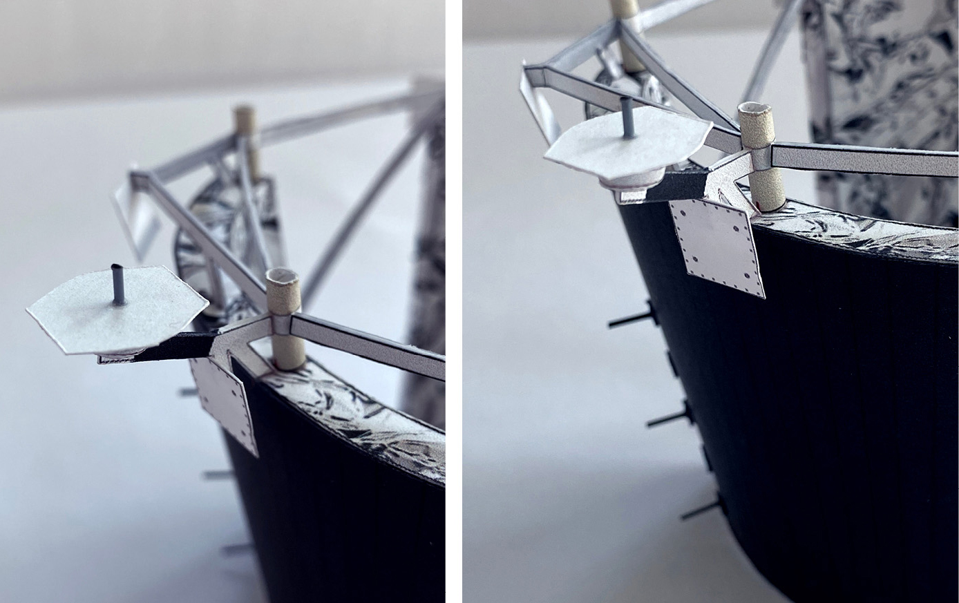
Step 85
Prepare 12 plastic broom straws according to instructions on pages 6 and 7 of the parts file. Glue 3 on each side of the radiators on a square as shown.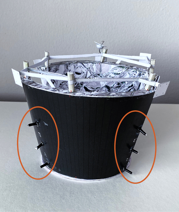
Step 86
Prepare the four (4) antennas using plastic broom straws according to instructions on page 10 of the parts file. Fold 99 into a “V” shape. Insert the antenna onto 99 and glue around 1/4 in (5 mm) from one end.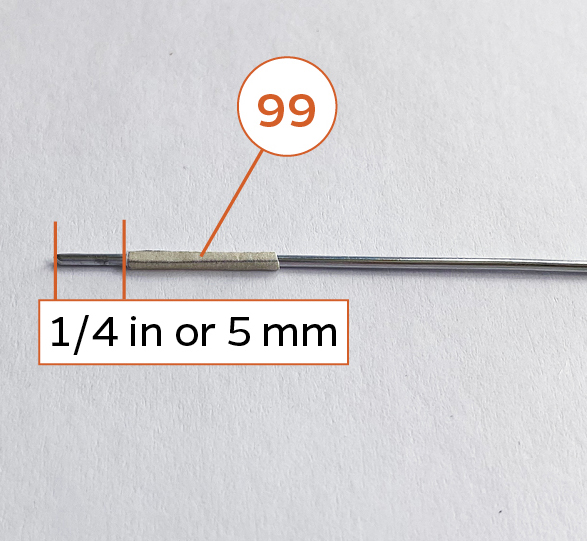
Step 87
Glue each antenna over part 87 on each of the four corners as shown. Using a hot glue gun is recommended.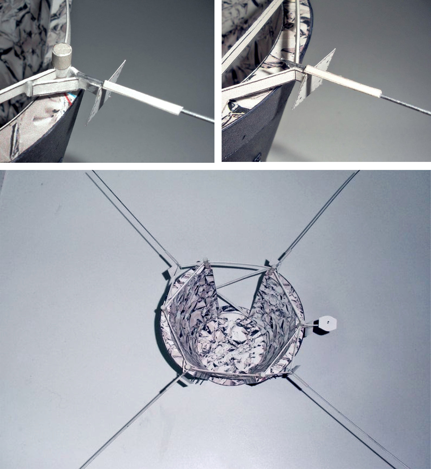
Step 88
Glue the heat shield onto the radiators. Start with the center poles on the two far ends (see arrows). The poles should align with the center of the pads on each end. The other four side poles should align with the other pads if the center pole is aligned. The position may not be perfect but should be close. This is why it was import to glue the poles onto the radiators and glue the radiators onto the base (part 72) using the lines or markers per the instructions.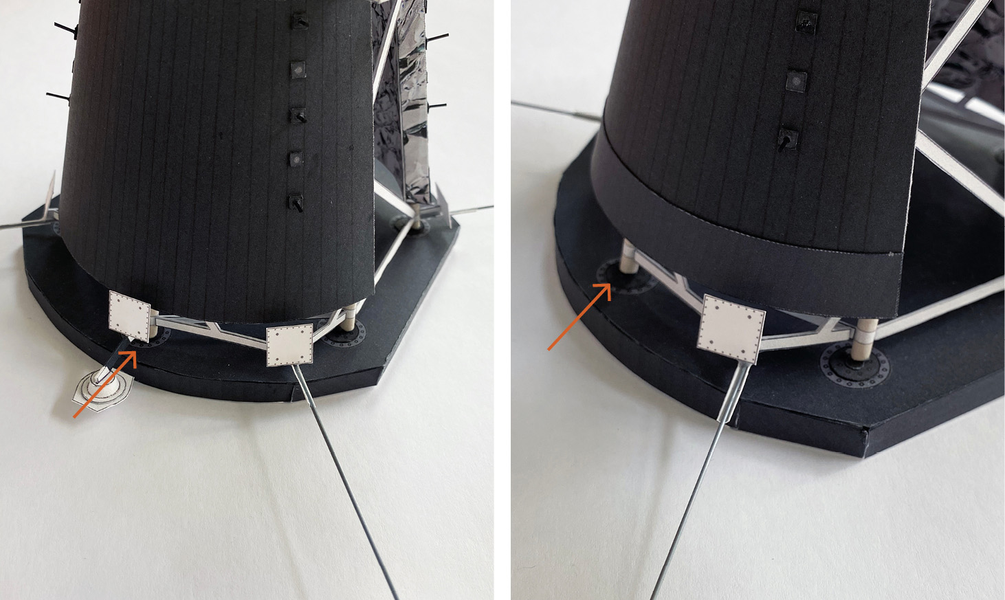
Step 89
Ready to glue onto the body.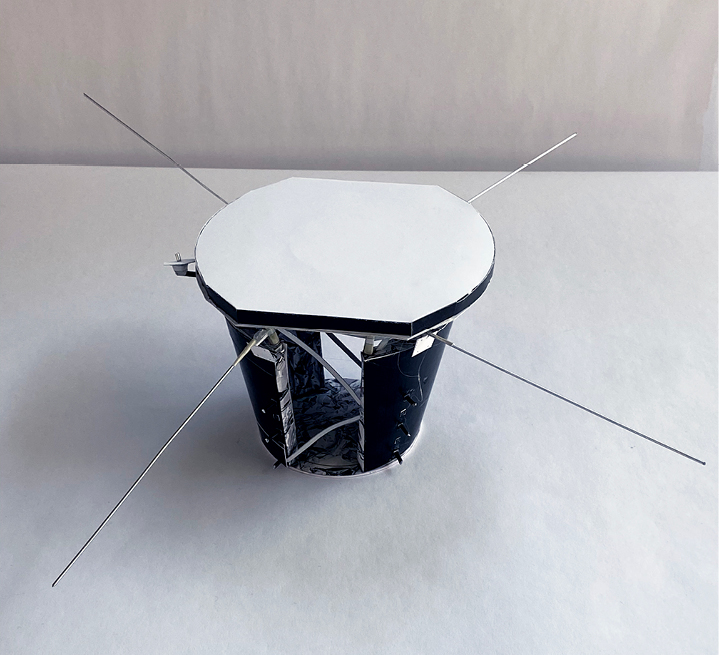
Step 90
The opening between the radiators should align with the solar panels (see above). The ring (72a) that you glued to back of 72 should fit on top of the circle (1a) that you glued onto the top of the body, and this will align the top perfectly.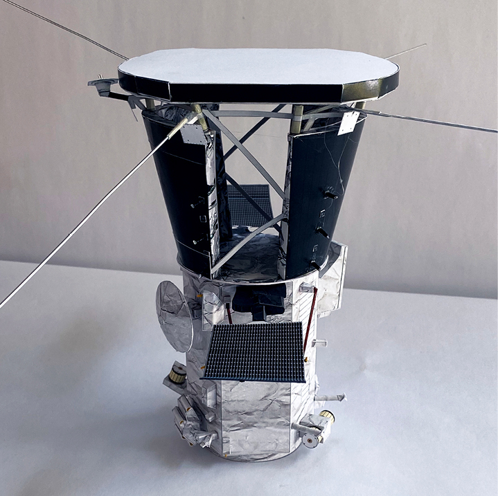
Step 91
The radiator with the two strips (77 and 78) should be positioned over the telescope (indicated by the blue arrows). The small antenna should be near the side with the high gain antenna (red arrow).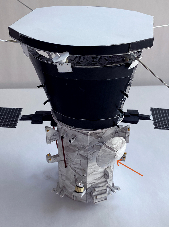
Step 92
Glue the magnetometer boom arm onto the hinge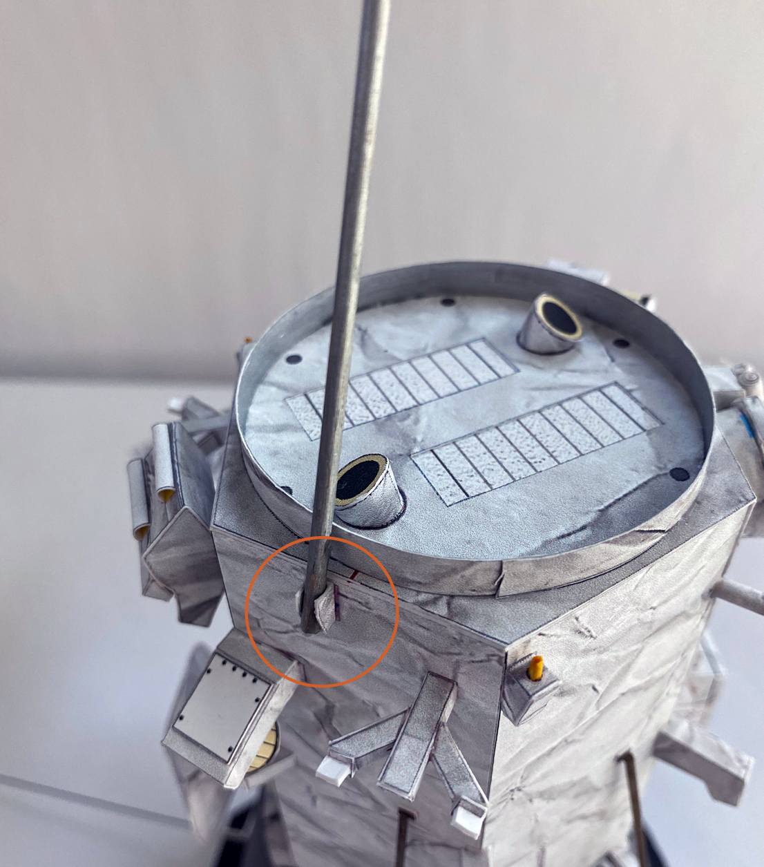
Step 93
The instruments on the arm should face away as shown.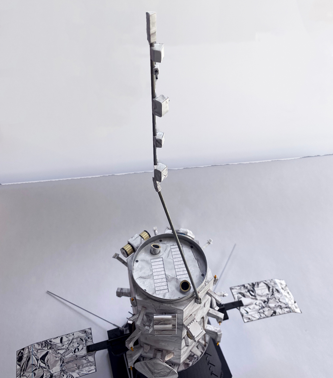
Step 94
You can create a stand for displaying your model with the magnetometer. See pages 11 and 12 of the parts file for instructions.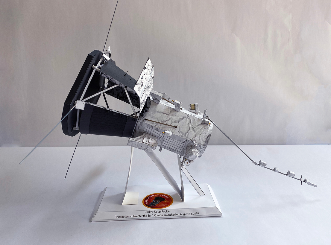
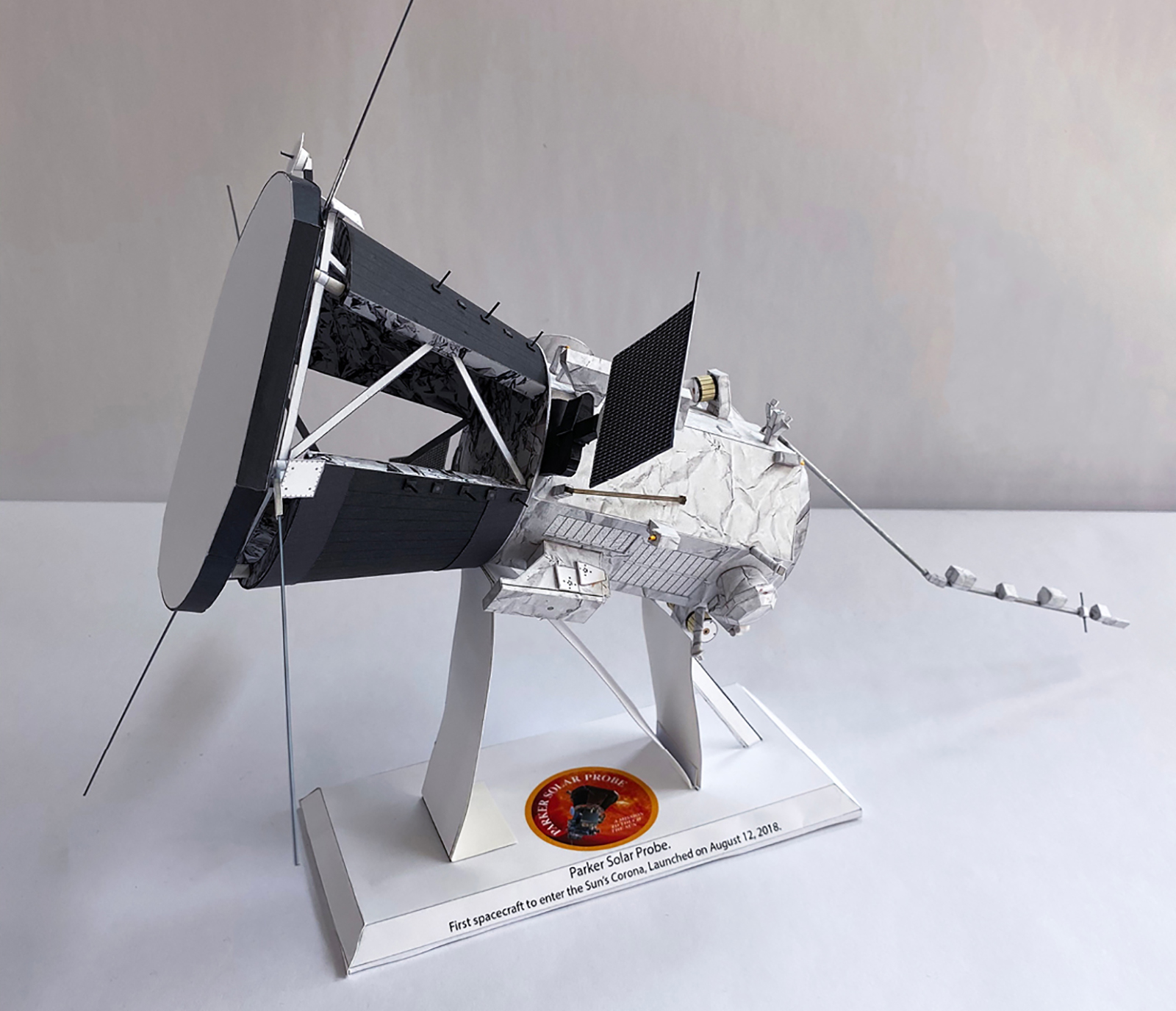
Step 95
Your model is done!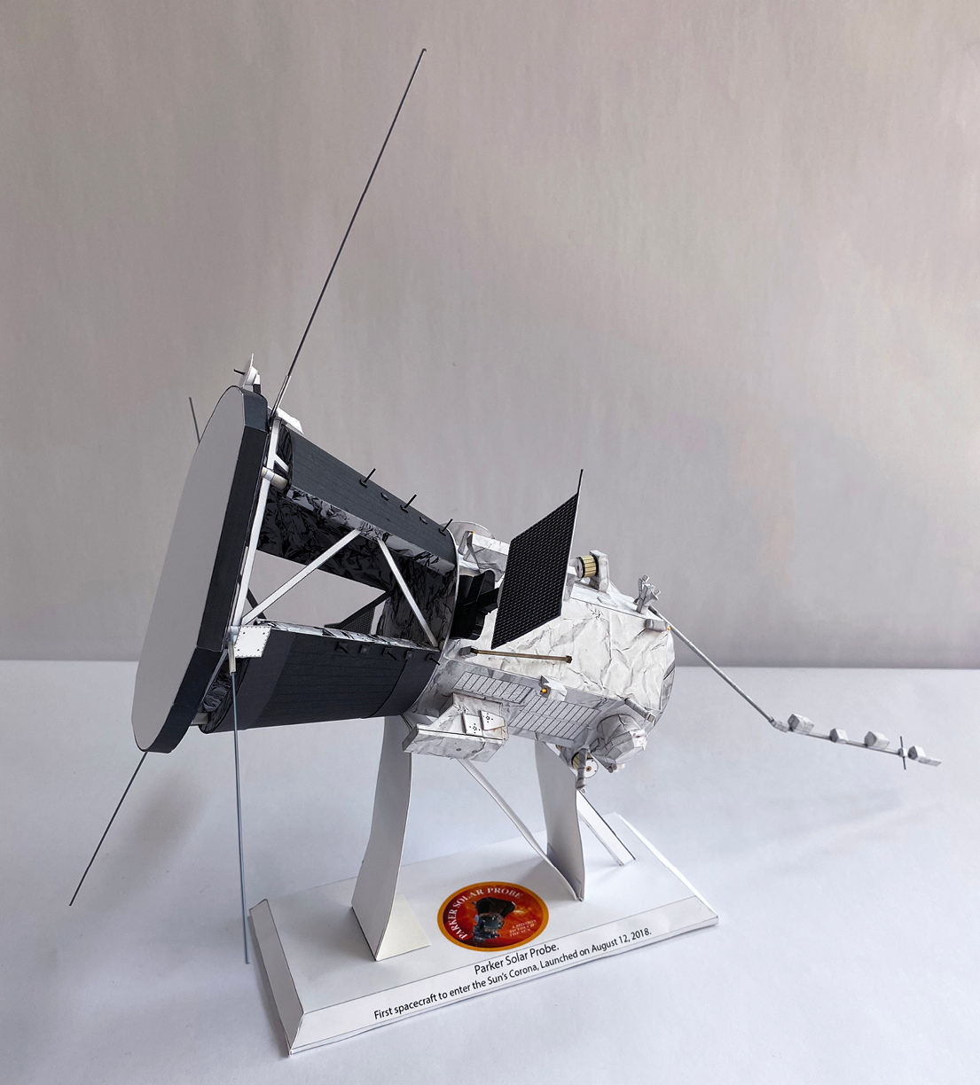

Parker Solar Probe paper model design by Zach PaperSat Design.
These materials may be distributed freely for educational or informational purposes,
under NASA’s Media Usage Guidelines.
Learn more at www.nasa.gov/multimedia/guidelines/index.html.
Parker Solar Probe AR Experience
Explore and manipulate the Parker Solar Probe spacecraft on your computer screen or scan the QR code to access an augmented reality version of the spacecraft on your cell phone!